Home
News
Downloads
Mailing lists
Documentation
FAQ
Screenshots
Recipes
Other GPSDs
Hardware
For GPS Vendors
Wish List
Hall of Shame
Troubleshooting Guide
Hacker's Guide
Application Compatibility References
History
Future

(Found on a Korean electronics dealer's website, edited to fix the English and remove promotional crap.)
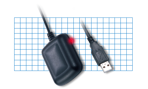
| Features: | |
|
1.
|
"SiRF Star II/LP" high performance and low power consumption chipset. |
|
2.
|
All-in-view 12-channel parallel processing. |
|
3.
|
Built-in active antenna. |
|
4.
|
High sensitivity to satellite signal. |
|
5.
|
Cold start under 45 seconds, average. |
|
6.
|
Superior urban canyon performance. |
|
7.
|
FoliageLock for weak signal tracking. |
|
8.
|
Build-in SuperCap to reserve system data for rapid satellite acquisition. |
|
9.
|
Supported NMEA 0183 command: GGA, GSA, GSV, RMC, GLL, VTG |
|
10.
|
Magnetic base for mounting on a car. |
|
11.
|
LED indicator
for GPS fix or not fix. LED OFF: Receiver is off LED ON : No fix, searching LED Flashing: Position Fixed |
|
12.
|
Non-slip on the bottom |
|
13.
|
USB interface connection port |
| Specifications: | |
| Interface | USB |
| Output Messages | NMEA0183 V2.2 protocol, and
supports commands: GGA, GSA, GSV, RMC, GLL, VTG |
| Datum | WGS84 |
| Hot Start | 8 sec.average |
| Warm Start | 38 sec.average |
| Cold Start | 48 sec.average |
| Altitude Limit | 18,000m(60,000 feet)Max. |
| Re-acquisition | 100ms |
| Velocity Limit | 515 meters/sec(1000knots)Max |
| Jerk Limit | 20 m/sec**3 |
| Horizontal Accuracy | 15m 2d RMS
without SA 10m 2d RMS WAAS enabled 1-5m DGPS corrected . |
| Vertical Accuracy | 40m 95% |
| Velocity Accuracy | 0.1m/sec 95% |
| Time Accuracy | 1us synchronized to GPS time |
| Dimension | 59 mm*47mm*21mm |
| Power Consumption | 90 mA(include Antenna) |
| Storage Temperature | -40C ~ 85C |
| Operation Temperature | -40C - 80C |
| Humidity | Up to 95% non - Condensing |
And this is from the spec sheet for the RoyalTek Sapphire, another SiRF-II-based GPS:
Altitude 18000 meters (60000 feet) max.
Velocity 514 meters / second max.
Jerk 20 meters / second, max.
Acceleration 4 G, max.
And now ESR tells a hardware-repair war story:
Older versions of the BU-303 (before mid-September 2004) had a design flaw. The device has an internal SuperCap, probably used to drive static RAM holding fix information when the unit is unplugged or powered down. The only thing holding the battery on the PCB was the solder on its leads.
Mechanical vibration and shock (from events like allowing the GPS to fall on the floor) could stress and eventually break the solder bond. If you start hearing a rattling noise from inside the BU-303 case, this has probably happened. The least-bad effect this can have is that the unit will start taking longer to acquire a first fix, because every time you plug it in will effectively be a cold start. If the loose SuperCap's contacts land in the right places, they can destroy or subtly derange the unit. At worst, this actually presented an explosion hazard.
After the battery has been loose for a while, the USB transciever in the device may go catatonic. You will know this has happened if the indicator LED still lights when the BU-303 is plugged in but the USB system on your laptop no longer sees the device. Check this by running lsusb(1); you should see a line that looks like this:
Bus XXX: Device YYY: ID 067b:2302 Prolific Technology Inc. PL2303 Serial Port
If you don't see this line, do not despair — it is actually possible to repair the unit. Here is how:
If you are lucky, your BU-303 now works again. But you need to be luckier than me; I got my USB subsystem to see it again, but it still doesn't send bits.